Drive unit DU-1
Reads the motor controller. Reports from the first run.
A sealed unit at the motor controller of an electric outboard, powered from its own battery. Prop rpm, speed, battery, current, temperatures, faults and position, joined to everything else known about the vessel.
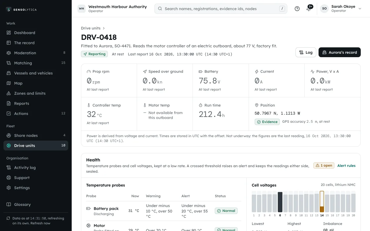
Drawn, indicative; working name. Portal with a demo organisation, data illustrative.
Supply, protection and temperature are working figures for the first build. The sample rate is what the two test logs show at source.
What it reads.
Four traces from two electric outboards, read at the motor controller. Both were run in place, tied up, to see which fields each gives. Not a trial, so no speed is shown.
Prop rpm
Electric outboard, 77 VRead from the motor controller several times a second. This controller also reports its limits: 7,350 rpm forward, 7,000 reverse, 150 A line current.
Current
Electric outboard, 77 VDrawn from a battery that held 76.3 to 76.9 V through the log, about a 77 V system.
Power
Electric outboard, 77 VBattery voltage times current, worked out on the platform and marked as derived. The outboard does not send it.
Duty cycle
Electric outboard, 51 VHow hard the controller drives the motor. This outboard also gives motor temperature and energy used; its battery sat near 51 V.
From a real test log of an electric outboard, 11 October 2026. Stationary runs: Electric outboard, 77 V, 50 rows over 18.7 s; Electric outboard, 51 V, 61 rows over 14.9 s.
Health, not just position.
The same unit watches the drive and the battery, and speaks up when something crosses a line.
Temperature probes
Battery pack, motor, controller, and ambient or bilge where fitted.
Every cell
Individual cell voltages from the battery management system, and the spread between them.
Alerts on thresholds
What crossed, by how much and for how long, with the readings either side sealed. A named person closes it.
Health reports
Per drive and per fleet: run time, energy, temperatures, cell balance, faults.
Only what each outboard gives.
DU-1 reads every field a controller offers. The platform shows only those, and a field an outboard does not give is shown as not available, never as zero.
From a real test log of an electric outboard, 11 October 2026.
Scroll across to see all columns.
| Field | Electric outboard, 77 V | Electric outboard, 51 V |
|---|---|---|
| Prop rpm | Available | Available |
| Speed over ground | Available | Available |
| Battery voltage | Available | Available |
| Current | Available | Available |
| Power (V x A)Derived on the platform | Available | Available |
| Motor temperature | Not available from this outboard | Available |
| Controller (ESC MOSFET) temperature | Available | Available |
| Duty cycle | Not available from this outboard | Available |
| Energy used | Not available from this outboard | Available |
| Energy regenerated | Not available from this outboard | Available |
| Position with GPS accuracy | Available | Available |
| Fault bits and fault text | Available | Not available from this outboard |
| Controller limits (max rpm, line current) | Available | Not available from this outboard |
Honest about its own data.
Every reading gets one quality level, shown with a word and an icon. Only Evidence is ever compared with a limit. DU-1 carries its own multi-band satellite receiver, 1.5 to 3 m expected, so it can reach Evidence. Working thresholds.
10 m or better, fix no older than 2 s.
From an Evidence fix, smoothed over 3 readings. In the test logs: 0 rows.
10 to 25 m.
Shown, not used for a limit decision. In the test logs: 0 rows.
25 to 100 m.
Shown greyed, never compared with a limit. In the test logs: 19 rows.
Worse than 100 m, or no fix.
Not shown as a figure. In the test logs: 92 rows.
Worked example: one of the stationary logs reports 3 to 6.6 km/h while the boat did not move. That is drift from a phone-grade fix of 98 m and worse, and it is marked Low or Unusable, never shown as a speed. Speed that sits still for more than 3 s while rpm changes by more than 10 % is marked stale (45 rows).
- Sample rate
- 2.5 to 4 Hz observed at source across the two test logs.
- Sealed at source
- Each reading is hashed as it is taken and sealed in batches of up to 10 s or 50 readings, signed on the unit and chained, so a gap in signal costs nothing.
- Agreement
- Two sources agree within 0.5 kn or 5 %, whichever is larger. Evidence needs at least one Evidence reading a second, and two agreeing sources where available.
- Time
- Stored in UTC with the offset kept. The test logs carry local time with no offset (BST, UTC+1), so the offset is added on import.
On the line, or in the boatyard.
With the outboard maker
Fitted at the motor controller before the outboard ships, so every outboard leaves reporting from its first run.
- Reads the controller the maker already fits
- Registered to the outboard serial
- Owner record from day one
Retrofit
Fitted on an electric outboard already in service, at the motor controller. Reads only; it never drives the motor.
- Power from the outboard battery via DC-DC
- No change to the controls
- Joins the vessel's existing record
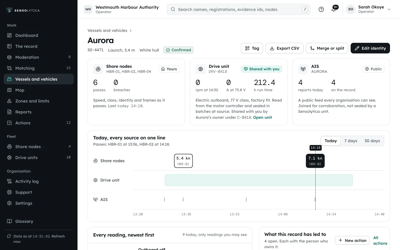
DRV-0418, in Aurora's record.
The drive unit's readings sit beside the shore node's and the AIS feed's, each sealed at source. Aurora, a 5.4 m electric launch, and DRV-0418 are illustrative.
- Placement
- On the outboard, at the motor controller. Fitted by the outboard maker or retrofitted
- Reads
- Prop rpm, speed over ground, battery voltage, current, power (V x A, derived), energy used and regenerated, motor and controller temperatures, duty cycle, controller limits, fault bits and fault text, position with its GPS accuracy, run time. Only what each outboard provides
- Power
- From the outboard battery via a DC-DC converter. 48 to 72 V class systems seen; the test logs show about 51 V and 77 V. Working
- Sample rate
- 2.5 to 4 Hz observed at source in the test logs
- Upload
- Over Bluetooth to a phone or its own uplink, in sealed batches. Logs from other apps can be imported from CSV
- Position
- Its own multi-band satellite receiver, 1.5 to 3 m expected, so readings can reach Evidence level
- Health
- Temperature probes and battery cell voltages where fitted, with alerts on thresholds
- Time
- Stored in UTC with the offset kept
- Protection
- IP67. Working
- Operating temperature
- Minus 25 to 85 °C. Working
- Sealing
- Each reading hashed at source; sealed in batches of up to 10 s or 50 readings, signed by the unit, chained
Every outboard you build, reporting.
Fit DU-1 at the motor controller and give the organisations that run them, your dealers and your own engineers one record of how each outboard is used.